
Description
Available for AutoCAD | AutoCAD LT
Contains Over 4,600 3D Pipe Symbols
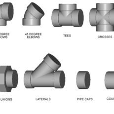
This comprehensive three dimensional piping symbols library contains over 4,600 solid model pipe fitting and valve symbols in several different material categories: carbon steel, ductile iron, pvc, and forged steel. This is not just a set of blocks, but a fully functional easy to use program that loads into AutoCad’s menu bar.
It’s easy to use:
The “3D Piping Symbols Library v1.1″ is a drafting tool to help piping draftsmen and designers quickly create 3D piping models in order to generate 2D plan, section and elevation drawings.
With a couple clicks of the mouse, you’ll be able to quickly insert the piping symbol you need to generate 3D piping layouts with ease. By utilizing a pull down menu and dialog boxes, this comprehensive block library organizes all of the symbols for easy and instant access.
3D Piping Symbols Include
- Ductile Iron Flanged
- Ductile Iron Mechanical Joint
- Carbon Steel Buttweld
- PVC Socket
- Forged Steel Threaded
- Forged Steel Socketweld
- Angle valves
- Ball valves
- Butterfly valves
- Check valves
- Diaphragm valves
- Gate valves
- Globe valves
- Needle valves
- Plug valves
- Expansion joints
Here’s what you get:
The “3D Piping Symbols Library version 1.1″ comes with a total of 4,749 symbols in the following categories:
Pipe fittings:
Ductile Iron Flanged Fittings – sizes 4″ through 48″
- ANSI/AWWA C110/A21.10
- Elbows – 11.25°, 22.5°, 30°, 45°, 90°
- Tees – full size & reducing
- 45° Wyes & laterals – full size & reducing
- Crosses
- Reducers – concentric & eccentric
- Blind flanges
Ductile Iron Mechanical Joint Fittings – sizes 4″ through 48″
- ANSI/AWWA C110/A21.10
- Elbows – 11.25°, 22.5°, 30°, 45°, 90°
- Tees – full size & reducing
- 45° Wyes & laterals – full size & reducing
- Crosses – full size & reducing
- Reducers – concentric & eccentric
Carbon Steel Buttweld Fittings – sizes 1/2″ through 24″
- ASME/ANSI B16.5
- Elbows – 90° & 45°
- Tees – full size & reducing
- Reducers – concentric & eccentric
- Pipe cap
- Flanges – 150# to 2500# – weld neck, threaded, slip-on, lap joint, blind (includes bolt holes & raised faces)
PVC Socket Fittings – sizes 3/8″ through 24″
- ASTM D2466
- Schedule 40 & 80
- Elbows – 11.25°, 22.5°, 30°, 45°, 90°
- Tees – full size & reducing
- 45° Wyes & laterals – full size & reducing
- Crosses – full size & reducing
- Reducers – concentric
- Caps
- Unions
- Couplings
- Flanges
Forged Steel Threaded Fittings – sizes 1/8″ through 4″
- 3000# & 6000# – ANSI/ASME B16.11
- Elbows – 45°, 90°
- Tees
- 45° Laterals
- Crosses
- Caps
- Unions
- Couplings
Forged Steel Socketweld Fittings – sizes 1/8″ through 4″
- 3000# & 6000# – ANSI/ASME B16.11
- Elbows – 45°, 90°
- Tees
- 45° Laterals
- Crosses
- Caps
- Unions
- Couplings
Here’s what you get:
The “3D Piping Symbols Library version 1.1″ comes with a total of 4,749 symbols in the following categories:
Angle valves – sizes 1/4″ through 8″
- Bronze – threaded & socketweld – class 125 – brand: Nibco
- Iron – flanged ends – class 125 – brand: Apollo
Ball valves – sizes 1/4″ through 12″
- Steel – flanged ends – class 150 & 300 – brand: Apollo
- Steel – threaded ends – brand: Nibco
- PVC – flanged & socket ends – brands: Asahi & Spears
- Iron – flanged ends – class 125 – brand: Apollo
Butterfly valves – sizes 1 1/2″ through 48″
- Steel – lug & wafer – handle or gear operators – brand: Crane
- Iron – double flange, lug & wafer – handle or gear operators – brand: Crane
- PVC – handle operator – brand: Asahi
Check valves – sizes 1/4″ through 48″
- Bronze – threaded & socketweld – class 125 – brand: Nibco
- PVC – ball check – socket ends – brand: Spears
- Steel – swing check, tilting disc check, wafer check – class 150, 300, 600 – brand: Crane
- Iron – swing check, wafer check – class 125 & 250 – brands: Crane & Nibco
Diaphragm valves – sizes 1/2″ through 10″
- PVC – flanged ends – brand: Asahi
Gate valves – sizes 1/4″ through 48″
- Bronze – threaded & socketweld ends – class 125 – brand: Nibco
- PVC – flanged & socket ends – brands: Asahi & Spears
- Steel – flanged & buttweld ends – class 150, 300, 600 – brand: Crane
- Iron – flanged & threaded ends – class 125 – brand: Nibco
- Iron wedge gate – flanged ends – brand: American Cast Iron Pipe Co.
Globe valves – sizes 1/8″ through 14″
- Bronze – threaded & socketweld ends – class 125 – brand: Nibco
- PVC – flanged & socket ends – brand: Asahi
- Steel – flanged & buttweld ends – class 150, 300, 600 – brand: Crane
- Iron – flanged ends – class 125 – brand: Nibco
Needle valves – sizes 1/4″, 3/8″, 1/2″
- PVC – socket ends – angle & straight – brand: Spears
Plug Valves – sizes 1/2″ through 24″
- Steel – flanged ends – class 150 & 300 – 2 way & 3 way – brand: Xomox
Expansion Joints:
- Manufacturer: Flexicraft
- Sizes: 1 1/4″ through 24″
- Style: Rubber arch – 1,2 & 3 arch; concentric & eccentric reducing – 150# flanged ends
How it works:
Once loaded in AutoCAD or AutoCAD LT, “Architect Library” will appear in the menu bar.
Step 1:
Choose a category and size of symbols from the pull-down menu.
Step 2:
A dialog box appears showing all of the available symbols with a description to the left. Choose the symbol you would like to insert and click on “OK”.
Step 3:
Insert the symbol in your layout and rotate to the desired position.
Details about the blocks:
- Each symbol is drawn as a solid model on layer zero with “bylayer” attributes.
- Once inserted, simply rotate the symbol into position and it will take on the characteristics of your current layer settings.
- Pipe fitting insertion points are located at the intersection of the pipe centerline.
- All flanged fittings and valves include bolt holes.
- All valves are shown with handles in the open position.
System requirements:
- Compatible with AutoCAD 2000 and newer
- 1.15 gig of available disc space required